Networking & Communications: Wireless Communication using a (i) HC_05 Bluetooth & (ii) nRF24L01 Radio Transceiver Module between Two Devices
Study 01: Remote Controlling of a Light Emitting Diode Using a Single HC_05 Bluetooth Module.
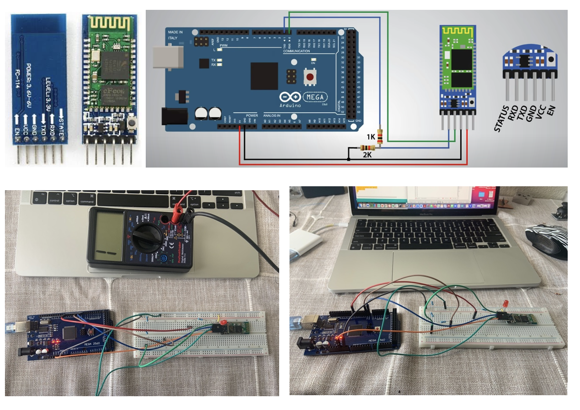
1. Specs of HC_05 blueetooth module:
From the literature, I found that this is a class-2 bluetooth module that has a SERIAL PORT PROFILE and cand be configured as either Master or Slave.
It requires a operating power supply of 3.3 DC Volt and 50mA. Most importantly its I/O pins are not 5V tolerant to interact with USB or any 5V operating MC chips.
So, a level converter or voltage divider using resistors must be used while interfacing with any MCs above 3.3V. It's a frequency of 2.4GHz ISM band and has a
sensitivity of ≤-84dBm at 0.1% BER. The working temperature of the module is -20 ~ +75Centigrade.
2. Circuit design:
For this week, I bought a ~$2 USD app from the i-phone's App Store. The purpose was to connect with my ciruitboard's (as shown below) LED and command it to be turned on/off. However, it didn't work. So, I had to turn to my MacBook.
I planned to connect my MacBook's bluetooh device to connect with my board's HC_05 bluetooh device. It worked but the connectivity doesn't stay more than 7-10 sec.
3. Baude rate influence & Commanding LED from Serial monitor:
Importantly, as shown in the video, the command to turn the LED on/off was done from the serial monitor of the IDE. 1. Must choose Baude rate: 38400 in the serial monitor to response to its LED ON/OFF (1/0)
I have to do the necessary coding (as shown in the video below) within this time-frame. Otherwise, I have to reconnect again. Since the Arduino MEGA'S Tx pin has a voltage logic of 5V and mu blutooth module HC_05 can handle 3.3 volts,
I had to make a voltage divider using resistors to save my module from being burnt. Example of a similar project with tutorial could be found at Arduino and HC-05 Bluetooth Module Complete Tutorial
4. How to upload the sketch and PASSWORD of bluetooh pairing:
While uploading the sketch, the RX/TX of the pinouts between Arduino Mega and Bluetooth module must be disconnected. Once the sketch is uploaded, then the RX/TX pins must be connected between the board and module to receive the Bluetooth command via my Macbook Pro. The Bluetooth connection password was “1234” for pairing with the Macbook.
5. Board constituents:
The circuit was designed as shown in the schematic with the pinouts. It had the resistor, LED, HC_05 bluetooth module, and a voltage divider. The Arduino MEGA's microcontroller was used to run the program.
Video clip:
6. Code:
//Code was retreived from howtomechatronics.com
#define ledPin 7
int state = 0;
void setup() {
pinMode(ledPin, OUTPUT);
digitalWrite(ledPin, LOW);
Serial.begin(38400); // Default communication rate of the Bluetooth module
}
void loop() {
if(Serial.available() > 0){ // Checks whether data is comming from the serial port
state = Serial.read(); // Reads the data from the serial port
}
if (state == '0') {
digitalWrite(ledPin, LOW); // Turn LED OFF
Serial.println("LED: OFF"); // Send back, to the phone, the String "LED: ON"
state = 0;
}
else if (state == '1') {
digitalWrite(ledPin, HIGH);
Serial.println("LED: ON");
state = 0;
}
}
Study 02: Sending Text Messages Wirelessly Between Two Devices (Arduino MEGA 2650 & UNO) using Two nRF24L01 Radio Transceivers.
1. Specs of nRF24L01 radio transceiver:
Using radio waves, this nRF24L01 transceiver operates. This single chip wireless transceiver is used to send and receive data using the radio waves. From literarure, I found that it transmits data - in air - at a speed up to 2Mbps.
It operates at around 3.3 volts. However, in a literature I found that "The power consumption of this module is just around 12mA during transmission, which is even lower than a single LED. The operating voltage of the module is from 1.9 to 3.6V,
but the good thing is that the other pins tolerate 5V logic, so we can easily connect it to an Arduino without using any logic level converters." I also found that it can communicate with six different modules, meaning it can be used for a mesh network architecture. It has a sensitivity of Its sensitivity of 85 dBm at 1 Mbps.
2. SPI Protocol (between MASTER & SLAVE computer) for data transmission:
The transceiver uses the SPI (Serial Peripheral Interface) protocol for communication or data transmission, which means SPI pins of a microcontroller needs to be connected to the corresponding SPI pins of NRF24L01 to interface with it. From the pinout image below:
(a) CSN pin (marked in YELLOW) is used for SPI protocol interfacing.
(b) CE pin is chip enable, it used to activate RX or TX mode.
(c) SCK pin is used for serial clock provider.
(d) MOSI pin is used to get data from a master microcontroller device and to send data to a slave device.
(e) MISO pin is used to get data from a slave device and to send data to master device.
(f) IRQ pin is used for interrupt data- no need of this pin connection for this project.
(g) VCC pin is used to apply 3.3V DC supply.
(h) GROUND is for grounding the circuit connection.
3. SPI protocol operates in a mode called Master-Slave node:
From a journal I found an application of these transceiver, where they mentioned that they used the nRF24L01 as sensors and commented:"The wireless
transmission part uses the NRF24L01 sensor and sends the data collected by the slave computer to the master computer for processing through the SPI protocol,
thereby realizing the data communication between the master computer and the slave computer and then realizing real-time display of the environmental data and intelligent alarm
function through the analysis of the received data. The SPI protocol works in a master-slave mode. This system uses one master one slave mode. The master device determines
the slave device through the enable signal so that the master-slave devices can be connected and the data transmission can be synchronized by the clock signal." The title of the work
is "Design and Implementation of Wireless Environment Monitoring System Based on STM32" by Qu Xilong, Liu Shengzong, Fu Sha, He Hong, Hu Ying, and Xiao Ley.
4. Circuit design:
The circuit was designed using Arduino MEGA and UNO along with a tranceiver for each of the PCBs. For stability, I added a 10 micro-faraday in between thr VCC and GROUND pins. Andres also advised me on it. However, without the capacitors (one in each board), the connection was also made.
Example of a similar project with tutorial could be found at nRF24L01 – How It Works, Arduino Interface, Code, Schematic
5. Challenges:
3.3 V didn’t work for my circuitries. I spent the whole day reassembling the circuit boards and pinnings. But nothing connected until
I had to supply 5V to the NRF24 transceivers in both the circuit boards to connect with each other. So, I would recommend adding the power supply pins
to the 5V pins of the Arduino MEGA & UNO.
Video clip:
6. Transmitter Code:
//Code was retreived from howtomechatronics.com
Library: TMRh20/RF24, https://github.com/tmrh20/RF24/